The rotary valve cylinder head has been around longer than the motorcycle, falling into, and out of favour on a regular basis. There’s a school of thought that says this system offers so many advantages that it could yet find its way into volume production.
To the engineering mind, the idea of bits of metal banging up and down, controlled by springing (whether metallic or pneumatic), all in the name of getting air into, and out of a combustion chamber, is rather crude to say the least. Poppet valves, in various configurations, soon became the system of choice for mass production, but several independent fertile minds were convinced that there had to be a better way – namely via a smoothly rotating cylindrical rotor, introducing mixture at one end and expelling it at the other. The chief proponent of this idea was Roland Cross, who largely overcame the great bugbear of the design – how to seal the valve itself. Yet Cross was merely following in the footsteps of many before him. The first production rotary valve engine, made by Crossley Bros. In Manchester, appeared in 1886 and remained in production until 1902. While fairly robust, it was a finicky system using springs to keep sealing pressure on the valve, creating two problems. If the spring pressure was too light, oil and gas would escape each time the engine fired, and if it were too heavy, the extra friction created would cause the valve to expand and partially seize.

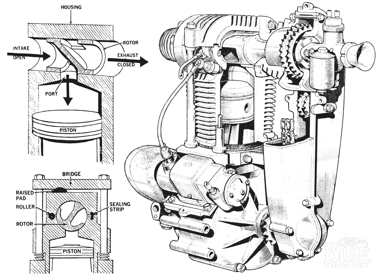
In his first versions, around 1922, Cross sought to eliminate these problems of sealing, friction and expansion – the latter by cooling the valve itself to provide dimensional stability. Cross’ answer to the lubrication issue was to design a valve incorporating a lip on the phosphor-bronze sleeve in the cylinder head in which the valve rotated. High-tensile phosphor-bronze has a certain amount of elasticity, and the design of the lip is such that a near-perfect seal, even capable of holding liquid such as petrol, is created. In reality however, excessive wear on the flexible lip proved impossible to overcome. It took more than ten years of development, financed by Cross’ successful endeavours in other fields of invention, before the system could be considered for production. Prototype engines using modified Rudge bottom ends were developed and were shown to be capable of over 8,500 rpm, at which point the big-end, not the valve, showed signs of failure. An oil-cooled Cross-Rudge was even entered for the 1935 Senior TT on the Isle of Man, but was withdrawn after problems in practice. Cross developed a split housing, whereby the valve sat in two halves of the cylinder head, with a separate bridge arrangement clamped to the crankcase by through bolts. A steel roller, looking like a normal gudgeon pin, acted as a hinge for the upper part of the housing, which had a sealing strip on the opposite side, making the housing slightly compressible. A raised pad on top of the housing, offset from the centre, bears against the under side of the retaining bridge. During peak pressure phases of the cycle – the compression and combustion strokes – the system reacts to the upward thrust of the cylinder and reverses it downwards, resulting in a tight seal. Coil springs at the base of the retaining studs maintain contact between the valve rotor and the lower part of the housing. The system allows for adequate lubricating (and cooling) oil to be used in the rotor without the traditional problem of leakage into the combustion area, but proved impractical for multi-cylinder designs because each individual cylinder would need a separate external ‘bridge’ set up.
Other variations on the same theme appeared in the late 1930s. A design produced by J and E Brown, using the basics Cross principles, incorporated a ‘sealing pad’, located between the rotor and the combustion chamber, which was pressed against the rotor by a spring ring, theoretically compensating for wear and expansion. Across the Atlantic, Merritt A. Zimmerman, a skilled sheet metal worker, produced a complete 250cc 45º v-twin using rotary valve heads in 1955. The valves were manufactured in 1.5% chrome cast iron with a nitrided surface, gear-driven and supported by ball bearings on both sides. Unlike the Cross design, the drive was to the exhaust end of the valve, allowing this high-temperature area to be cooled by the oil in the gear tower. The valve was sealed at the entry to the combustion chamber with a ‘port shoe’ made in 12% lead phosphor bronze, held in place against the valve by a bronze ring retained by a steel circlip. The engine ran cleanly to 9,000 rpm, where it developed 39.5 bhp, but its designer claimed 12,000 rpm and 45 bhp was easily attainable, although only for short periods. Far from being a workshop curio, the Zimmerman twin, mounted in a conventional chassis of his own design, was used regularly in US Enduros and Scrambles, ridden by Norman Smith, but its creator firmly resisted all proposals to put the unit into production.
In contrast to the spherical rotary valve, another school of thought existed, the cone-type valve, first successfully built by Frank Aspin in Lancashire in 1937. His 250cc motorcycle engine was shown to be capable of 14,000 rpm. Aspin’s conical valve, co-axial with the cylinder, occupied the area of the conventional combustion chamber. The new combustion chamber became a cavity in the wall of the cone, aligned with the exhaust and inlet ports. Aspin’s prototypes were demonstrated to achieve exceptionally clean burning of the mixture, low fuel consumption and capable of running very high compression ratios on low-grade fuel. There was, of course, a problem – that of lubrication between the valve cone and its mating surface – exacerbated by the alternating periods of low and high pressure during the engine’s cycles. Aspin tried all sorts of things to solve the inherent flaws – cones with thin flexible edges, cones with sealing rings, cones floating and controlled by spring pressure or located positively in precision bearings – all came at a price in terms of performance, reliability, and manufacturing cost. Eventually, many of the inherent problems were solved with a variable-speed valve developed by Aspin in the 1960s, and as the early days of unleaded petrol and ever-more stringent emission rules dawned, this design, with its virtual insensitivity to knock, detonation or pre-ignition and ability to run on low-octane fuel, was seen as the way of the future. Indeed, a 4.5 litre Aspin-valve truck engine developed for the British Army in the late 1940s would run happily on creosote! Among others, NSU experimented with the Aspin principle in the mid 1950s, while Norton seriously looked at a Cross arrangement for use on the works Manx engines.
Local knowledge
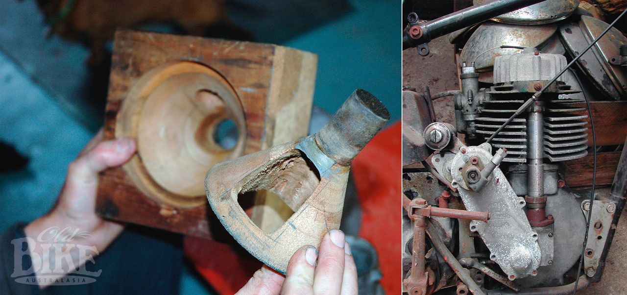
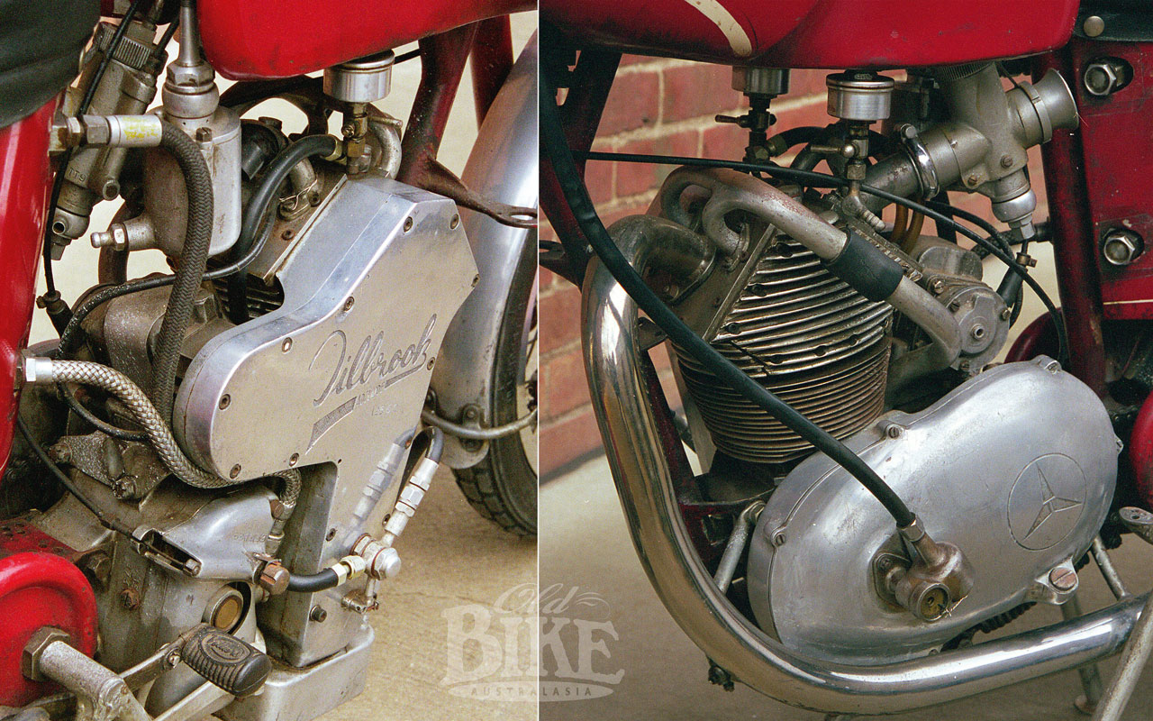
Out here in the Colonies, advocates of the rotary valve, in all its varied forms, have been hard at work for many decades. Many variations on the principle were built and tried, and some, like the curious ‘Rotacette’ (based on a KSS Velocette engine) and the Tilbrook (Based on a Villiers two-stoke bottom end) survive. Little is known about the Rotocette, now owned by Sydney Velo enthusiast Chris Roberts, other than it is believed to have been built in the defunct Sydney firm of Kirby Engineering sometime prior to 1950. The Aspin-principle engine sat for many years in the grubby premises of Ryan & Honey in Hunt Street, Sydney. The Tilbrook had a hardened and ground crankshaft inside the Villers crankcases, driving a train of gears in a handsome casting on the right hand side. Atop the barrel sat Rex Tilbrook’s version of a twin rotary valve head, with the valves rotating at one-quarter engine speed. Barrel and head were fastened by springs and the unit showed usable power from 8,000 to 12,000 rpm, but offered now real advantage of Tilbrook’s well-developed two strokes, and was shelved after just one test run.
In the 1950s, Adelaide engineer David Dunstan designed and built a rotary valve, fuel-injected head for the 6-cylinder 138 Grey Holden engine. Dunstan’s design varied from conventional rotary valve thinking, where the valve turned at half engine speed, in that it rotated at one-quarter engine speed, with two intake passages, 180º apart on opposite sides of the valve, for each individual cylinder. Both intake and exhaust gases used the same valve port in alternation, reducing cooling problems and friction losses. The valve itself was hollow, with cooling water passing through the centre. The cylinder head is split horizontally to accommodate the valve, with sealing rings set into the head to seal the unit. The prototype Dunstan Holden conversion first appeared in 1954, fitted to a speedboat, and had six separate heads with a single valve passing through all of them. Disaster awaited however, when the boat’s hull broke up and sank in fifty feet of salt water, where it remained for a week until salvaged. The engine was rebuilt with a one-piece head and a dry sump, and in dynamometer tests, running on nitro-methane, pushed out 200 bhp at 7,500 rpm. Despite the 12:1 compression ratio, the engine was shown to run happily on anything from 75 octane petrol to pure methanol, with no increases to jet sizes. The valve itself was lubricated by petrol-oil mist, as on two strokes, but there were plans to change this to a pressure lubrication system. Dunstan’s engine, like many other rotary valve designs, never made it to the planned mass production stage, due more to the ultra conservative thinking within the automotive industry than for any technical reason.
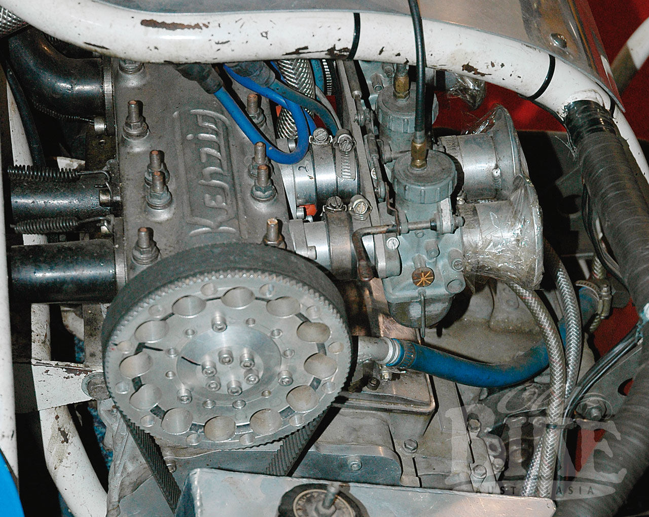
The Dunstan principle was used to create a rotary valve head for a Honda CB750 engine, fitted to a racing kneeler-style sidecar by Queenslander Greg Kenzig. The unit looks almost standard at first glance, with four Kehin carburettors and four exhaust pipes in the usual places. From the sides, the valve housing is clearly visible, running across the cylinder head and turning at half engine speed. Tragically, after surviving a battle with cancer, Greg Kenzig lost his life at the Isle of Man TT in 2007, when a competing motorcycle crashed into the spectator area where he was standing. Today, his outfit is on display at the Australian Motorcycle Museum at Haigslea, west of Brisbane.
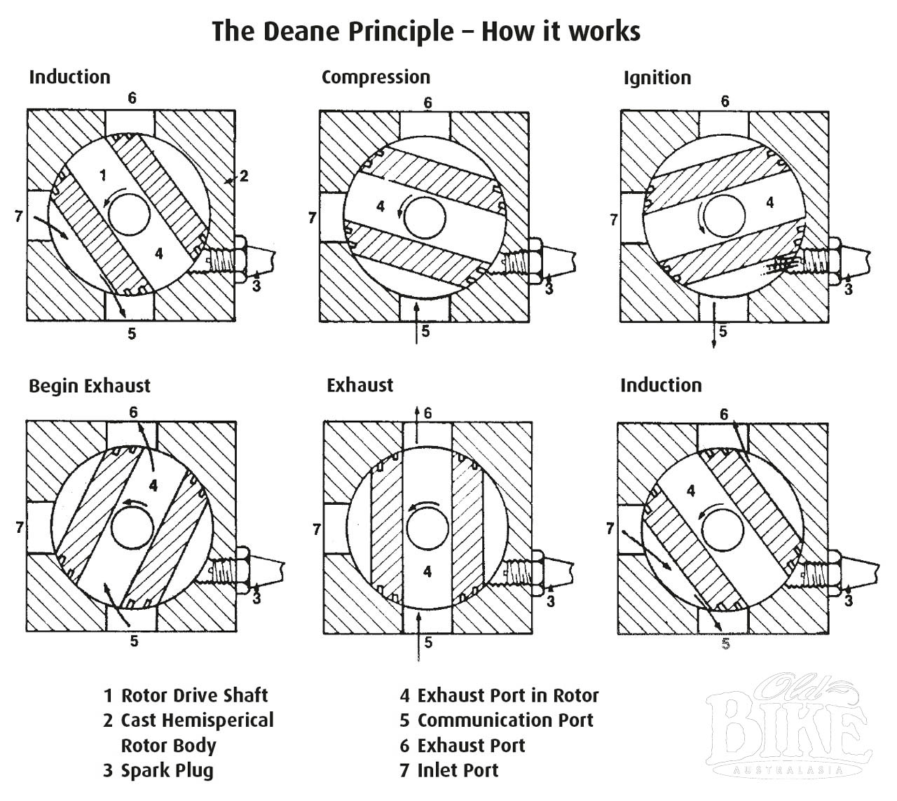
The Deane Rotary valve used a ball-like steel rotor equipped with piston-style rings, revolving at quarter engine speed in a housing in the cylinder head. Ports in the head and slots in the rotor permitted the system to charge the cylinder, compress, fire and exhaust the mixture, with compression ratios of up to 100:1 possible. Developed by three Victorian engineers, Ron Deane, Harry Bishop and Charles Beard, the prototype head was installed on a 500cc Norton in the early 1970s, almost doubling the power and fuel economy. One curious feature was the absence of an exhaust pipe, the spent gases being expelled out the top of the cylinder head, almost inaudibly. Beard said the effectiveness of the design is demonstrated by the absence of heat and exhaust gas noise, providing that the expanding gases have spent most of their energy driving the piston down, before leaving the cylinder head. A later version of the head was fitted to a Honda SL100 motorcycle, running a compression ratio of 12:1, and then to a four-cylinder Ford Cortina block. Despite considerable publicity, the project founded due to its inability to attract a financial partner.
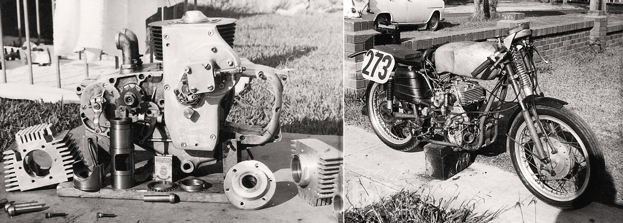
In Sydney, Peter Gabelish began experimenting with rotary valve heads for motorcycles around 1971. His first exercise involved a conversion for a 125cc MV Agusta road racer, originally a single overhead camshaft design. Gabelish developed a three-piece aluminium-alloy head, with a 2-inch diameter dynamically-balance rotor, driven by chain and gears and supported on bronze bearings. With a 15;1 compression ratio and running on methanol, the engine buzzed to 11,000. Later, a one-piece head was made, with the rotor running in needle-roller bearings, and with the compression lowered to 10.5:1, the engine would operate quite happily on mineral turpentine. Some years later, after linking up with toolmaker Aub Vial, and with some input from the legendary Phil Irving, a larger version of the head was developed and fitted to a Yamaha XT500, retaining the original 34mm carburettor and using the standard cam chain drive to spin the rotor. Such was the efficiency of the combustion process that the ignition timing was able to be reduced to 13 degrees. The converted Yamaha received extensive publicity, and Gabelish and Vial formed a company, GV Technology Ltd, to market the concept. With financial backing from Perth businessman Laurie Connell, a dedicated test workshop was set up in Sutherland, in Sydney’s south, and by 1986 looked set to take on the world after a technology agreement was entered into with the Ford Motor Company in USA. After promising a great deal, the project failed to proceed for various reasons. The XT 500 Yamaha still exists and the engine still runs. Aub Vial is restoring the MV, and indeed the rotary project was resurrected five years ago, using a WR450 Yamaha as the basis.
In 1997, Sydney company Bishop Innovations entered into a top-secret agreement with Ilmor Engineering (makers of the V10 Mercedes Benz Formula One engine) to develop a rotary valve head. The Bishop design was developed from the Gabelish design. Arthur Bishop’s first involvement with rotary valves was through the Gabelish/Vial partnership. Much work was done using single cylinder test engines in Sydney and at Ilmor’s UK base, with an increase in power of around 10% achieved, as well as a saving of 16kg on the complete engine. Bishop claimed to have solved traditional sealing problems with new and still-secret technology, and were all set to produce the heads that would have powered the 2004 McLaren Mercedes. Then in stepped the governing body, the FIA, ruling that only engines with reciprocating valves were permitted, and the project was dead in the water.
Today, all is once again quiet on the rotary valve front, but the question remains. For what appears to be such a great system, when will a rotary valve engine reach mass production?
Story: Jim Scaysbrook • Photos: Peter Gabelish archives, Dennis Quinlan